Here is some information for LT1, LS1, Vortec 4.8, 5.3, 6.0 wiring harnesses. There should be enough here to get you going in the right direction. Some of these I have pictures of completed harnesses I have modified for easy installation. I have a lot of pictures so please be patient and let them load. If you find this information useful, or have suggestion on something to add, let me know, I will try to get it done. My goal is to help the hobbyist to be able to complete a harness transformation by them self. I would only hope you send the PCM to me when it comes time for it. I do not charge for ANY information.
Thanks! -Brendan.
|
|||||
|
|
|||||

1992 to 1997 LT1 5.7 and L99 4.3 Wiring Harness Info Includes: Camaro/Firebird, Corvette, Caprice/Impala, Roadmaster
1996 to 1999 Vortec 4.3/5.0/5.7/7.4L Harness Schematics and INFO.
1998 to 2002 Camaro/Firebird harness Wiring Info -New PCM Pinout info specific to 98, 99-02 F-body. 3/30/2013
2001 Vortec 8.1L Info
2004 Pontiac GTO Wiring Harness Info - Wiring harness info specific to the 2004 GTO LS1
1999 to 2007 Vortec 4.8/5.3/6.0 Harness Wiring Info TONS OF INFO HERE, Please Read all the pages linked. New page on Air Conditioning Controls! 9/8/2020
2007 to 2013 Vortec 4.8/5.3/6.0/6.2 Harness Information - New Harness Modification INFO added 11/6/2012! ECM Info HERE!
2010 to 2011 Camaro L99 - LS3 Information, Wiring, and so on
2014-2016 Gen5 L83 L86 Wiring Harness Information - Adding info over next few weeks as I get stuff done. 2/9/2021
www.lsxharness.com - Adam will rework most LS1, Vortec Truck, and F-Body LT1 Harnesses
www.hotrodharness.com - Purchase new harnesses for swaps, Vortec 4.3, 5.7, 7.4, LS, LT, Truck lots of applications
For parts list for fuse block, obd2 diagnostic port, and wiring instructions, click here!
Typical 'External' Connections.....this applies to most any GM wiring harness.....
12v+ Battery Connection - The computer requires a battery constant connection. This is so the PCM can remember learned information about the engine over time. This includes idle control, fuel trims, and transmission adapts. Its very important that the battery hot wires (usually ORANGE) are hot all the time.
Key 12v+ Connection* - The PCM also gets 12V+ from a KEY HOT source. This is what 'powers up' the PCM. Its important that this key hot power, along with power to injectors, coils, and so on, STAY HOT when cranking over the engine. Some accessory positions on key switches ARE NOT HOT when cranking. This also includes older vehicles that had POINTS ignition. Even the COIL wire on some of those went dead when cranking. This is because when cranking the coil was boosted to 12v+ through the R terminal on the starter solenoid. After cranking, power was restored to the coil through a resistor, lowering voltage to 6 volts.
Fuel Pump Relay Control - The computer on GM fuel injection systems is designed to control a fuel pump relay. The computer does this by supply a 12v+ (POSITIVE) signal to the relay. The signal is only present for two seconds at key on. Fuel pump operation resumes when cranking over. The PCM ONLY commands it back on when the PCM reads that the engine is turning over. So, if there is a condition where there is a bad crank sensor, fuel pump will come on, turn off, and will not turn on when cranking.
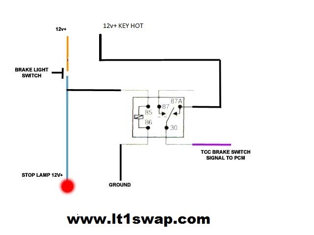
Brake Switch Signal - For automatics with lock up converter, the PCM needs signal when brake pedal is pressed. However, the signal needed is opposite how you're brake lights work. The PCM wants 12v+ constant on this wire when brake IS NOT pressed, and OPEN Circuit when the brake IS pressed. If you vehicle was equipped with a lockup trans to begin with, you probably already have the proper normally closed switch mounted by your brake light switch. If you do not, you can use a relay to perform the same thing. On most relays, there are 5 terminals, 2 of them turn the relay ON when provided ground/power. There are then a normally open leg and a normally closed leg on the relay and a supply. By feeding 12v+ on the supply leg, and hooking the Brake Switch Signal wire to the normally closed leg, you will now have the correct signal for the PCM. When the brake is pressed, 12v+ flows to brake lights, tap into this wire, and run it to the relay to turn the relay on. This will cause the normally closed leg to become open, thus turning OFF the 12v+ signal to the PCM. When you release the brake pedal, the relay will turn OFF, and then feed 12v+ to the PCM.
VSS Signal - This wire is a 4000 pulse per mile signal from the PCM used by some aftermarket speedometers. This can also be use for the electric cruise control boxes used on early 90s GM cars & trucks. PCM can be programmed to match tire size and axle ratio for you're swap, so this signal is calibrated. Chrysler/Jeep vehicles typically need a 8000 pulse/mile signal to run the speedometer.
TACH Signal - On 1993 LT1 with distributors, this comes from the negative side of the coil. Later LT1 and on LS1, Vortec 4.8/5.3/6.0 this comes from the PCM, which generates this signal for a aftermarket tachometer. The stock LS tach signal is 4 cylinder type signal. This can be programmed as 4, 6, or 8 cylinder signal. Some 2003+ LS PCM's tach signal is not strong enough, and needs boosted, see this link.
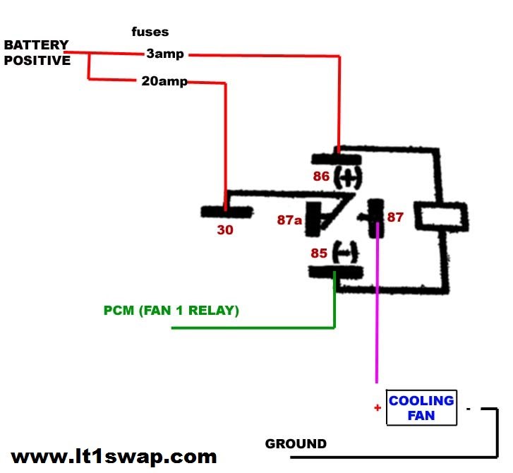
Fan Controls 1,2 - GM PCM's typically will control electric fans, usually 2. The PCM will supply the (negative) or GROUND signal to turn on fan relays. YOU CAN NOT DIRECTLY CONNECT PCM FAN CONTROL WIRE TO FANS. YOU MUST USE A RELAY.
How to wire up a fan relay....using a (negative) or GROUND control from PCM
Wire going to terminal 30 & 87 should be 10-12 gauge to handle the current draw of the cooling fan. Terminals 85 & 86 can use 16-22 gauge just fine. Relay coil draws less then 1 amp. Make sure the ground for the cooling fan is a good one, also ensure there is a good ground from the battery ( - ) side to the frame.
Use this schematic to wire up a DUAL SPEED fan such as the Ford Taurus fan. This uses a 5 terminal relay for the on on the right in this schematic. When the HIGH speed kicks in, it removes power from the first relay. This prevents power from being applied to both wires of the fan at the same time.

If you want your fan or fans to turn on with a/c compressor, you can use the following wiring to do that. The label "TO FAN RELAY CONTROL (-) can splice into the wire from the PCM to the FAN relay. This way the PCM can still control the fan when A/C is off, or when A/C is commanded on, the fan comes on right away.

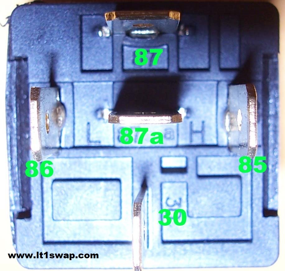
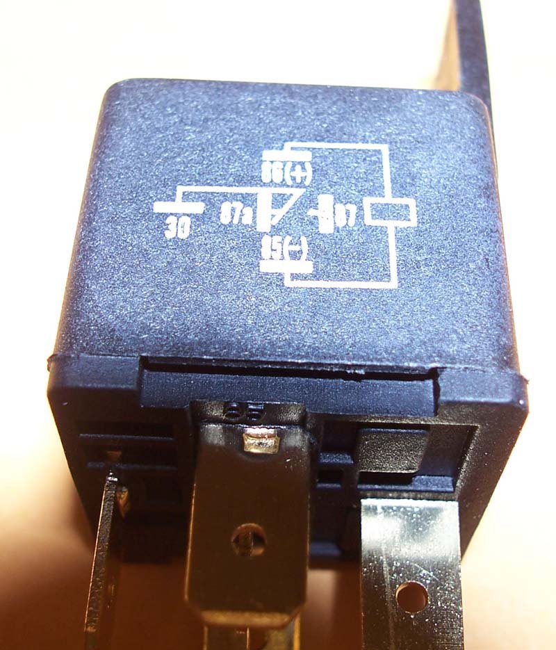
Here are some pictures of a typical automotive relay that can be found at most parts stores.
Contact Info