I get a lot of questions about use the stock fuse block. I do not usually use this method, but I'm going to put some info out here for you all. If you have any issues with this let me know, I'm going strictly off wiring schematics to figure this out for you.
1999-2002 FUSE BLOCKS and HARNESSES
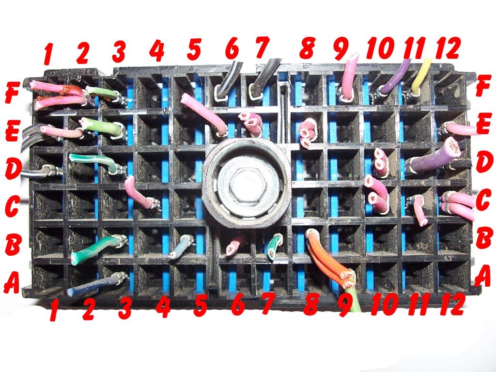
C1- B11 - RED this wire feeds 12v Battery+ to ignition switch, hot at all times.
C1 - A9 - PINK - this wire is FROM ignition switch, hot in RUN, START. This powers up fuses on block.
C3 - F1 - GRAY - Power feed to fuel pump.
In addition to those connections, you need to connect C100 pin C, Pink, to 12v+ RUN/START source. This wire feeds the Transmission Solenoids and PCM. The fuse for this wire is NOT in the underhood fuse block. The fuse was located in the instrument panel fuse block in the 99+ pickups. You need to use a 10A fuse for this wire and hook to a RUN/START 12v+ source. This wire runs from C100 Pin C to underhood fuse block C2 - E2. Inside the fuse block, it turns around and comes back out on C2 - F2. F2 then runs to the PCM and Transmission. You could also take the PINK wire out of C2-F2 and move it to location that has key hot 12v+. One such is C2-B9 which is key hot for ELECTRIC THROTTLE CONTROL module. On a DBC harness, this will be empty, put a fuse in, move the wire. If you are using DBW, you may have to find another location, or share the fuse.
2003-2007 FUSE BLOCKS and HARNESSES

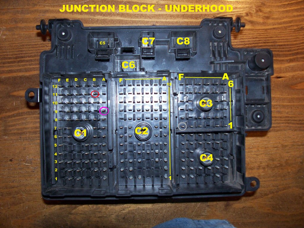
The method above for the 1999-2002 will NOT work for the 2003+ fuse blocks. Things move around. The bottom of the fuse block may look a little different, but the two we are concerned with, C1, and C2 should be in the same location. This info SHOULD be good for 2003-2007 fuse blocks. I wrote this info looking at 2003 schematics, and quickly compared to 2005, and 2007 schematics and all show the same.
C7 - A - RED this wire feeds 12v Battery+ FROM fuse (IGN B 40A) TO ignition switch, hot at all times.
C1 - A9 - PINK - this wire is FROM ignition switch, hot in RUN, START. This powers up multiple fuses on underhood block and activates the IGN 1 Relay. *SAME as prior years
C1 - A3 - YELLOW this wire is used if you want to use the PCM to control the starter. 12v+ on this wire sends a crank request to the PCM to engage the starter. The PCM will not engage starter if: in gear (uses range switch on trans to determine gear), engine running (not confirmed but seems logical), or security not removed.
Like before, this fuse block also DOES NOT power the transmission solenoids, or pin 75 KEY HOT 12v+ to the PCM. On the 03+ power comes from IGN 0 Fuse in the instrument panel, to underhood block C1 pin C9. Inside the fuse block, it turns around, comes out on C2 pin E11 (two pink wires, one to Trans Pin E, other to PCM Pin 75) Just like 99-02, you need this circuit powered up. You can power the wire at C1-C9, or move the wire at C2-E11 to a position with power in it. I'm not aware of any extra circuits you can use in the underhood fuse block.