|
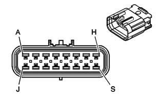
C100 I/P Harness to Engine Harness (w/o JL4)
|
|||||||||||||||

|

|
||||||||||||||
| Connector Part Information |
15316037 | Connector Part Information | 15422562 | ||||||||||||
| 14-Way F GT Mixed (BK) | 14-Way M GT Mixed (BK) | ||||||||||||||
| Pin | Wire Color | Circuit No. | Function | Pin | Wire Color | Circuit No. | Function | ||||||||
| A | OG | 52 | Blower Motor High Control | A | OG | 52 | Blower Motor High Control | ||||||||
| B | L-BU | 72 | Medium 2 Blower Motor Control | B | L-BU | 72 | Medium 2 Blower Motor Control | ||||||||
| C | YE | 60 | Blower Motor Low Control | C | YE | 60 | Blower Motor Low Control | ||||||||
| D | TN | 63 | Blower Motor Medium 1 Control | D | TN | 63 | Blower Motor Medium 1 Control | ||||||||
| E | OG | 1732 | Inadvertent Power Supply Voltage | E | OG | 1732 | Inadvertent Power Supply Voltage | ||||||||
| F | D-GN | 1049 | Class 2 Serial Data | F | D-GN | 1049 | Class 2 Serial Data | ||||||||
| G | YE | 710 | Class 2 Serial Data (Early Production) | G | YE | 710 | Class 2 Serial Data (Early Production) | ||||||||
| H | -- | -- | Not Used | H | -- | -- | Not Used | ||||||||
| J | D-GN/WH | 817 | Vehicle Speed Signal (K34) | J | D-GN/WH | 817 | Vehicle Speed Signal | ||||||||
| K | BN/WH | 419 | MIL Control | K | BN/WH | 419 | MIL Control | ||||||||
| L | L-BU/BK | 396 | Cruise Control Engaged Signal (K34) | L | L-BU/BK | 396 | Cruise Control Engaged Signal | ||||||||
| M | D-GN | 83 | Cruise Control Inhibit Signal (K34) | M | D-GN | 83 | Cruise Control Inhibit Signal | ||||||||
| N | L-BU | 1122 | Class 2 Serial Data | N | L-BU | 1122 | Class 2 Serial Data | ||||||||
| P | L-GN | 66 | A/C Request Signal | P | L-GN | 66 | A/C Request Signal (C60) | ||||||||
|
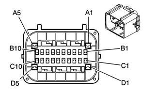
C100 Engine Harness to I/P Harness (JL4)
|
|||||||||||||||

|
|
||||||||||||||
| Connector Part Information | 15355480 | Connector Part Information | 15355479 | ||||||||||||
| 30-Way F GT 150 SLD (BK) | 30-Way M GT 150 SLD (BK) | ||||||||||||||
| Pin | Wire Color | Circuit No. | Function | Pin | Wire Color | Circuit No. | Function | ||||||||
| A1 | L-BU | 1122 | Class 2 Serial Data | A1 | L-BU | 1122 | Class 2 Serial Data | ||||||||
| A2 | RD/BK | 4042 | Battery Positive Voltage | A2 | RD/BK | 4042 | Battery Positive Voltage | ||||||||
| A3 | OG | 52 | Blower Motor High Control | A3 | OG | 52 | Blower Motor High Control | ||||||||
| A4 | L-BU | 72 | Medium 2 Blower Motor Control | A4 | L-BU | 72 | Medium 2 Blower Motor Control | ||||||||
| A5 | L-BU | 2206 | Traction Control Preference Switch Signal | A5 | L-BU | 2206 | Traction Control Preference Switch Signal | ||||||||
| B1 | GY | 626 | 5-Volt Reference | B1 | GY | 626 | 5-Volt Reference | ||||||||
| B2 | L-BU | 1059 | Steering Wheel Position Sensor Signal 1 | B2 | L-BU | 1059 | Steering Wheel Position Sensor Signal 1 | ||||||||
| B3 | L-BU | 1764 | Steering Wheel Position Signal B | B3 | L-BU | 1764 | Steering Wheel Position Signal B | ||||||||
| B4 | D-BU | 84 | Cruise Control Set/Coast Switch Signal (K34) | B4 | D-BU | 84 | Cruise Control Set/Coast Switch Signal (K34) | ||||||||
| B5 | D-GN | 1049 | Class 2 Serial Data | B5 | D-GN | 1049 | Class 2 Serial Data | ||||||||
| B6 | YE | 710 | Class 2 Serial Data (Early Production) | B6 | YE | 710 | Class 2 Serial Data (Early Production) | ||||||||
| B7 | BN/WH | 419 | MIL Control | B7 | BN/WH | 419 | MIL Control | ||||||||
| B8 | D-GN | 2087 | Yaw Rate Sensor 5-Volt Reference | B8 | D-GN | 2087 | Yaw Rate Sensor 5-Volt Reference | ||||||||
| B9 | L-BU | 2088 | Yaw Rate Sensor Low Reference | B9 | L-BU | 2088 | Yaw Rate Sensor Low Reference | ||||||||
| B10 | L-GN/BK | 5352 | Sensor Self Test Signal Circuit | B10 | L-GN/BK | 5352 | Sensor Self Test Signal Circuit | ||||||||
| C1 | OG/BK | 556 | Steering Wheel Position Sensor Low Reference | C1 | OG/BK | 556 | Steering Wheel Position Sensor Low Reference | ||||||||
| C2 | L-GN | 1763 | Steering Wheel Position Signal A | C2 | L-GN | 1763 | Steering Wheel Position Signal A | ||||||||
| C3 | WH | 1765 | Steering Wheel Position Marker Pulse Signal | C3 | WH | 1765 | Steering Wheel Position Marker Pulse Signal | ||||||||
| C4 | -- | -- | Not Used | C4 | -- | -- | Not Used | ||||||||
| C5 | L-GN | 66 | A/C Request Signal | C5 | L-GN | 66 | A/C Request Signal | ||||||||
| C6 | GY/BK | 87 | Cruise Control Resume/Accel Switch Signal (K34) | C6 | GY/BK | 87 | Cruise Control Resume/Accel Switch Signal (K34) | ||||||||
| C7 | GY | 397 | Cruise Control On Switch Signal (K34) | C7 | GY | 397 | Cruise Control On Switch Signal (K34) | ||||||||
| C8 | D-BU | 716 | Yaw Rate Sensor Signal | C8 | D-BU | 716 | Yaw Rate Sensor Signal | ||||||||
| C9 | L-BU | 715 | Lateral Accelerometer Signal | C9 | L-BU | 715 | Lateral Accelerometer Signal | ||||||||
| C10 | YE | 5353 | Yaw Rate Frequency | C10 | YE | 5353 | Yaw Rate Frequency | ||||||||
| D1 | PK | 1339 | Ignition 1 Voltage | D1 | PK | 1339 | Ignition 1 Voltage | ||||||||
| D2 | YE | 60 | Blower Motor Low Control | D2 | YE | 60 | Blower Motor Low Control | ||||||||
| D3 | TN | 63 | Blower Motor Medium 1 Control | D3 | TN | 63 | Blower Motor Medium 1 Control | ||||||||
| D4 | L-BU | 1320 | CHMSL Supply Voltage/Stop Lamp Supply Voltage | D4 | L-BU | 1320 | CHMSL Supply Voltage/Stop Lamp Supply Voltage | ||||||||
| D5 | OG | 1732 | Inadvertent Power Supply Voltage | D5 | OG | 1732 | Inadvertent Power Supply Voltage | ||||||||
|
C101 Engine Harness to Chassis Harness (w/o JL4)
|
|||||||||||||||

|
|
||||||||||||||
| Connector Part Information | 15326666 | Connector Part Information | 15326667 | ||||||||||||
| 16-Way F GT 280 SLD 5.8 (BK) | 16-Way M GT 150 SLD 5.8 (BK) | ||||||||||||||
| Pin | Wire Color | Circuit No. | Function | Pin | Wire Color | Circuit No. | Function | ||||||||
| A | YE/BK | 1827 | Vehicle Speed Signal | A | YE/BK | 1827 | Vehicle Speed Signal | ||||||||
| B | GY | 2709 | 5-Volt Reference B | B | GY | 2709 | 5-Volt Reference B | ||||||||
| C | TN | 2759 | Low Reference (Late Production) | C | TN | 2759 | Low Reference (Late Production) | ||||||||
| BK | 2759 | Low Reference (Early Production) | BK | 2759 | Low Reference (Early Production) | ||||||||||
| D | D-GN | 890 | Fuel Tank Pressure Sensor Signal | D | D-GN | 890 | Fuel Tank Pressure Sensor Signal | ||||||||
| E | PU | 333 | Brake Fluid Level Switch Signal (Heavy Duty) | E | PU | 333 | Brake Fluid Level Switch Signal (Heavy Duty) | ||||||||
| F | PU | 1589 | Fuel Level Sensor Signal | F | PU | 1589 | Fuel Level Sensor Signal | ||||||||
| G | -- | -- | Not Used | G | -- | -- | Not Used | ||||||||
| H | WH | 1310 | EVAP Canister Vent Solenoid Control | H | WH | 1310 | EVAP Canister Vent Solenoid Control | ||||||||
| J | RD/WH | 140 | Battery Positive Voltage (Late Production) | J | RD/WH | 140 | Battery Positive Voltage (Late Production) | ||||||||
| OG | 140 | Battery Positive Voltage (Early Production) | OG | 140 | Battery Positive Voltage (Early Production) | ||||||||||
| K | L-BU | 1122 | Class 2 Serial Data | K | L-BU | 1122 | Class 2 Serial Data | ||||||||
| L-S | -- | -- | Not Used | L-S | -- | -- | Not Used | ||||||||
|
C101 Chassis Harness to Engine Harness (JL4)
|
|||||||||||||||
|
|
|
||||||||||||||
| Connector Part Information | 15355480 | Connector Part Information | 15355479 | ||||||||||||
| 30-Way F GT 150 SLD (BK) | 30-Way M GT 150 SLD (BK) | ||||||||||||||
| Pin | Wire Color | Circuit No. | Function | Pin | Wire Color | Circuit No. | Function | ||||||||
| A1 | D-GN | 2087 | Yaw Rate Sensor 5-Volt Reference | A1 | D-GN | 2087 | Yaw Rate Sensor 5-Volt Reference | ||||||||
| A2 | L-BU | 2088 | Yaw Rate Sensor Low Reference | A2 | L-BU | 2088 | Yaw Rate Sensor Low Reference | ||||||||
| A3 | L-GN/BK | 5352 | Sensor Self Test Signal Circuit | A3 | L-GN/BK | 5352 | Sensor Self Test Signal Circuit | ||||||||
| A4 | YE/BK | 1827 | Vehicle Speed Signal | A4 | YE/BK | 1827 | Vehicle Speed Signal | ||||||||
| A5 | GY | 2709 | 5-Volt Reference B | A5 | GY | 2709 | 5-Volt Reference B | ||||||||
| B1 | TN | 2759 | Low Reference | B1 | TN | 2759 | Low Reference | ||||||||
| B2 | WH | 1765 | Steering Wheel Position Marker Pulse Signal | B2 | WH | 1765 | Steering Wheel Position Marker Pulse Signal | ||||||||
| B3-B4 | -- | -- | Not Used | B3-B4 | -- | -- | Not Used | ||||||||
| B5 | D-GN | 890 | Fuel Tank Pressure Sensor Signal | B5 | D-GN | 890 | Fuel Tank Pressure Sensor Signal | ||||||||
| B6 | PU | 333 | Brake Fluid Level Switch Signal (Heavy Duty) | B6 | PU | 333 | Brake Fluid Level Switch Signal (Heavy Duty) | ||||||||
| B7 | PU | 1589 | Fuel Level Sensor Signal | B7 | PU | 1589 | Fuel Level Sensor Signal | ||||||||
| B8 | GY | 626 | 5-Volt Reference | B8 | GY | 626 | 5-Volt Reference | ||||||||
| B9 | L-BU | 1059 | Steering Wheel Position Sensor Signal 1 | B9 | L-BU | 1059 | Steering Wheel Position Sensor Signal 1 | ||||||||
| B10 | L-BU | 1764 | Steering Wheel Position Signal B | B10 | L-BU | 1764 | Steering Wheel Position Signal B | ||||||||
| C1 | D-BU | 716 | Yaw Rate Sensor Signal | C1 | D-BU | 716 | Yaw Rate Sensor Signal | ||||||||
| C2 | L-BU | 715 | Lateral Accelerometer Signal | C2 | L-BU | 715 | Lateral Accelerometer Signal | ||||||||
| C3 | YE | 5353 | Yaw Rate Frequency | C3 | YE | 5353 | Yaw Rate Frequency | ||||||||
| C4 | WH | 1310 | EVAP Canister Vent Solenoid Control | C4 | WH | 1310 | EVAP Canister Vent Solenoid Control | ||||||||
| C5 | RD/WH | 140 | Battery Positive Voltage | C5 | RD/WH | 140 | Battery Positive Voltage | ||||||||
| C6 | L-BU | 1122 | Class 2 Serial Data | C6 | L-BU | 1122 | Class 2 Serial Data | ||||||||
| C7 | TN/BK | 464 | Delivered Torque Signal | C7 | TN/BK | 464 | Delivered Torque Signal | ||||||||
| C8 | OG/BK | 463 | Requested Torque Signal | C8 | OG/BK | 463 | Requested Torque Signal | ||||||||
| C9 | L-BU | 2206 | Traction Control Preference Switch Signal | C9 | L-BU | 2206 | Traction Control Preference Switch Signal | ||||||||
| C10 | OG/BK | 556 | Steering Wheel Position Sensor Low Reference | C10 | OG/BK | 556 | Steering Wheel Position Sensor Low Reference | ||||||||
| D1 | L-GN | 1763 | Steering Wheel Position Signal A | D1 | L-GN | 1763 | Steering Wheel Position Signal A | ||||||||
| D2 | BK | 2150 | Ground | D2 | -- | -- | Not Used | ||||||||
| D3 | RD/BK | 4042 | Battery Positive Voltage | D3 | RD/BK | 4042 | Battery Positive Voltage | ||||||||
| D4-D5 | -- | -- | Not Used | D4-D5 | -- | -- | Not Used | ||||||||
| Fuse Block - Underhood - C1 | |||||

|
15319897 | ||||
| 68-Way F Metri-Pack 280 Series- Flexlock (L-GY) | |||||
| Pin | Wire Color | Circuit No. | Function | ||
| A1 | -- | -- | Not Used | ||
| A2 | YE/BK | 625 | Starter Enable Relay Control | ||
| A3-A7 | -- | -- | Not Used | ||
| A8 | PU | 420 | TCC Brake Switch/Cruise Control Release Signal | ||
| A9 | L-GN | 275 | Park Neutral Position Switch Park Signal | ||
| A10 | RD/WH | 440 | Battery Positive Voltage (Late Production) | ||
| RD/WH | 440 | Battery Positive Voltage (Late Production) | |||
| OG | 440 | Battery Positive Voltage (Early Production) | |||
| OG | 440 | Battery Positive Voltage (Early Production) | |||
| A11-A12 | -- | -- | Not Used | ||
| B1 | -- | -- | Not Used | ||
| B2 | D-GN | 1433 | Neutral Safety Back Up Switch Signal | ||
| B3 | -- | -- | Not Used | ||
| B4 | PK | 139 | Ignition 1 Voltage | ||
| PK | 139 | Ignition 1 Voltage (4.8L/5.3L/6.0L) | |||
| B5-B9 | -- | -- | Not Used | ||
| B10 | PU | 806 | Crank Voltage | ||
| B11-B12 | -- | -- | Not Used | ||
| C1 | PU | 6 | Starter Solenoid Crank Voltage | ||
| C2 | BK | 1250 | Ground | ||
| C3 | PK | 339 | Ignition 1 Voltage | ||
| C4 | PK | 139 | Ignition 1 Voltage | ||
| PK | 139 | Ignition 1 Voltage | |||
| C5-C9 | -- | -- | Not Used | ||
| C10 | PK | 239 | Ignition 1 Voltage | ||
| C11-C12 | -- | -- | Not Used | ||
| D1-D3 | -- | -- | Not Used | ||
| D4 | PK | 139 | Ignition 1 Voltage | ||
| PK | 139 | Ignition 1 Voltage | |||
| D5-D9 | -- | -- | Not Used | ||
| D10 | PK | 239 | Ignition 1 Voltage | ||
| PK | 239 | Ignition 1 Voltage (4.8L/5.3L/6.0L) | |||
| D11 | -- | -- | Not Used | ||
| D12 | D-GN/WH | 459 | A/C Compressor Clutch Relay Control (C60) | ||
| E1 | PK | 539 | Ignition 1 Voltage | ||
| PK | 539 | Ignition 1 Voltage | |||
| E2 | PK | 439 | Ignition 1 Voltage | ||
| E3 | -- | -- | Not Used | ||
| E4 | PK | 139 | Ignition 1 Voltage | ||
| PK | 139 | Ignition 1 Voltage | |||
| E5 | -- | -- | Not Used | ||
| E6 | RD/WH | 140 | Battery Positive Voltage (Late Production) | ||
| OG | 140 | Battery Positive Voltage (Early Production) | |||
| E7-E9 | -- | -- | Not Used | ||
| E10 | PK | 239 | Ignition 1 Voltage | ||
| PK | 239 | Ignition 1 Voltage | |||
| E11-E12 | -- | -- | Not Used | ||
| F1 | PK | 1539 | Ignition 1 Voltage | ||
| PK | 1539 | Ignition 1 Voltage | |||
| F2 | -- | -- | Not Used | ||
| F3 | PK | 1020 | Ignition 0 Voltage | ||
| PK | 1020 | Ignition 0 Voltage | |||
| F4 | D-GN | 1329 | Horn Fuse Supply Voltage | ||
| F5-F7 | -- | -- | Not Used | ||
| F8 | D-GN/WH | 465 | Fuel Pump Relay Control - Primary | ||
| F9-F10 | -- | -- | Not Used | ||
| F11 | D-GN | 1324 | Backup Lamp Supply Voltage (Late Production) | ||
| L-GN | 1324 | Backup Lamp Supply Voltage (Early Production) | |||
| F12 | D-GN | 59 | A/C Compressor Clutch Supply Voltage (C60) | ||
PCM PINOUTS below submitted from a customer. sometime around 2004 gm changed colors on some wires, so you could see red/white for constant hot instead of orange. Also some low reference wires maybe a different color.
2006 Chevy express van
Powertrain Control Module (PCM) Blue C1
Wire Color
Circuit No.
Function
1 BLACK/WHITE, 1551, Ground
2 LIGHT GREEN, 1867, 12-Volt Reference
3 PINK/BLACK, 1746, Fuel Injector 3 Control
4 LIGHT GREEN/BLACK, 1745, Fuel Injector 2 Control
5-6 Not Used
7 GREY, 2705, 5-Volt Reference 1
8 GREY, 2701, 5-Volt Reference 1 (w/o JL4 - DBC applications)
9-10 Not Used
11 LIGHT BLUE, 1876, Knock Sensor 2 Signal
12 YELLOW, 573, CKP Sensor Signal
13, ORANGE/BLACK, 463, Requested
Torque Signal (JL4)
14 ORANGE/BLACK, 1061, UART Serial Data (w/JL4 - DBW applications)
15 DARK BLUE/WHITE, 774, UART Serial Data (w/JL4 - DBW applications)
16 Not Used
17 DARK BLUE, 1225, Transmission Fluid Pressure Switch Signal B
18 ORANGE, 1226, Transmission Fluid Pressure Switch Signal C
19 PINK, 439, Ignition 1 Voltage (PCM)
20 RED/WHITE, 440, Battery Positive Voltage
21 PURPLE, 574, Low Reference
22 Not Used
23 TAN, 2759, Low Reference
24 BLACK/WHITE, 1551, Ground
25 TAN, 1671, HO2S Low Signal - Bank
2 Sensor 2
26 TAN, 1667, HO2S Low Signal - Bank 2 Sensor 1
27 BLACK/WHITE, 1551, Ground
28 TAN/WHITE, 1669, HO2S Low Signal
- Bank 1 Sensor 2
29 TAN, 1664, HO2S Low Signal - Bank 1 Sensor 1
30-31 NOT USED
32 TAN/WHITE, 771, Transmission Range Switch Signal A
33 PURPLE, 420, TCC Brake Switch/Cruise Control Release Signal
34 WHITE, 776, Transmission Range Switch Signal P
35 Not Used
36 TAN, 1744, Fuel Injector 1 Control
37 YELLOW/BLACK, 846, Fuel Injector 6 Control
38 Not Used
39 YELLOW/BLACK, 625, Starter Enable
Relay Control
40 BLACK/WHITE, 1551, Ground
41 EGR PURPLE NOT USED
42 electric fan 1
43 ORANGE/BLACK, 877, Fuel Injector 7 Control
44 LIGHT BLUE/BLACK, 844, Fuel Injector 4 Control
45 Not Used
46 GREYY, 2709, 5-Volt Reference 2
47 EGR GREY NOT USED
48 GREY, 597, 5-Volt Reference 1
49-50 Not Used
51 DARK BLUE, 496, KS 1 Signal
52 Not Used
53 TAN, 2762, Low Reference
54 ORANGE/BLACK, 469, Low Reference
55 EGR BROWN NOT USED
56 Not Used
57 RED/WHITE, 440, Battery Positive Voltage
58 DARK GREEN, 1049, Class 2 Serial Data
59 Not Used
60 TAN, 2752, Low Reference (w/o JL4 - DBC)
61 PINK/BLACK, 632, Low Reference
62 Not Used
63 BLACK, 2755, Low Reference
64 BLACK/WHITE, 1551, Ground
65 PURPLE, 1670, HO2S High Signal -
Bank 2 Sensor 2
66 PURPLE, 1666, HO2S High Signal - Bank 2 Sensor 1
67 BLACK/WHITE, 1551, Ground
68 PURPLE/WHITE, 1668, HO2S High
Signal - Bank 1 Sensor 2
69 PURPLE/WHITE, 1665, HO2S High Signal - Bank 1 Sensor 1
70 BROWN, 1174, Oil Level Switch
Signal
71 Not Used
72 YELLOW, 772, Transmission Range Switch Signal B
73 BROWN/WHITE, 633, CMP Sensor Signal
74 YELLOW, 410, ECT Sensor Signal
75 PINK, 1020, Ignition Voltage (PCM)
76 TAN/WHITE, 845, Fuel Injector 5 Control
77 DARK BLUE/WHITE, 878, Fuel Injector 8 Control
78 Not Used
79 WHITE, 687, 3-2 Shift Solenoid Valve Control (5.3L)
80 TAN, 2761, Low Reference ECT SENSOR
Powertrain Control Module (PCM) Green C2
1 BLACK/WHITE, 1551, Ground
2 BROWN, 418, TCC PWM Solenoid Valve Control
3-4 Not Used
5 TAN/BLACK, 464, Delivered Torque
Signal (JL4)
6 ORANGE/BLACK, 1228, PC Solenoid Valve High Control
7 EGR ORANGE NOT USED
8 LIGHT BLUE/WHITE, 1229, PC Solenoid Valve Low Control
9 DARK GREEN/WHITE, 465, Fuel Pump Relay Control - Primary
10 WHITE TACH
11-12 Not Used
13 LIGHT BLUE/BLACK, 396, Cruise
Control Engaged Signal (w/o JL4)
14 Not Used
15 ORANGE, 225, Generator Turn On Signal
16 Not Used
17 DARK GREEN/WHITE, 2523, A/C
Request Signal (C60)
18-19 Not Used
20 PURPLE, 401, Signal Low - Front
21 YELLOW, 400, Signal High - Front
22 ORANGE/BLACK, 1230, AT ISS High Signal (4L80-E/4L85-E)
23 DARK BLUE/WHITE, 1231, AT ISS Low Signal (4L80-E/4L85-E)
24 DARK BLUE, 411, TP Sensor Signal (w/o JL4)
25 TAN, 472, IAT Sensor Signal
26 PURPLE, 2121, IC 1 Control
27 ORANGE, 2127, IC 7 Control
28 LIGHT BLUE/WHITE, 2126, IC 6 Control
29 DARK GREEN/WHITE, 2124, IC 4 Control
30 Not Used
31 YELLOW, 492, MAF Sensor Signal
32 LIGHT GREEN , 432, MAP Sensor Signal
33 Electric fan 2
34 DARK GREEN/WHITE, 428, EVAP
Canister Purge Solenoid Valve Control
35-36 Not Used
37 DARK GREEN , 83, Cruise Control
Inhibit Signal (w/o JL4 or Early Production JL4)
38 Not Used
39 ORANGE, 631, 12-Volt Reference
40 BLACK/WHITE, 1551, Ground
41 EGR WHITE NOT USED
42 TAN/BLACK, 422, TCC Solenoid Valve Control (5.3L)
43 DARK GREEN/WHITE, 459, A/C
Compressor Clutch Relay Control (C60)
44 Not Used
45 WH, 1310, EVAP Canister Vent
Solenoid Valve Control
46 BROWN/WHITE, 419, MIL Control
47 YELLOW/BLACK, 1223, 2-3 Shift Solenoid Valve Control
48 LIGHT GREEN, 1222, 1-2 Shift Solenoid Valve Control
49 YELLOW/BLACK, 1827, Vehicle Speed
Signal
50 DARK GREEN/WHITE, 817, Vehicle Speed Signal (w/o JL4)
51 YELLOW/BLACK, 1227, TFT Sensor Signal
52 PURPLE, 5035, HO2S Heater Low
Control - Bank 1 Sensor 2
53 YELLOW, 5036, HO2S Heater Low
Control - Bank 2 Sensor 2
54 PURPLE, 1589, Fuel Level Sensor
Signal
55 DARK GREEN, 603, A/C Low Pressure
Switch Signal (C60)
56 Not Used
57 TAN, 470, Low Reference
58 TAN/WHITE, 331, Oil Pressure
Sensor Signal
59 PURPLE, 806, Crank Voltage
60 BROWN, 2129, Low Reference
61 BROWN/WHITE, 2130, Low Reference
62 GREY, 773, Transmission Range Switch Signal C
63 PINK, 1224, Transmission Fluid Pressure Switch Signal A
64 DARK GREEN, 890, Fuel Tank
Pressure Sensor Signal
65 Not Used
66 PURPLE/WHITE, 2128, IC 8 Control
67 ORANGE/WHITE, 2122, IC 2 Control
68 DARK GREEN, 2125, IC 5 Control
69 LIGHT BLUE, 2123, IC 3 Control
70-71 Not Used
72 LIGHT BLUE, 5038, HO2S Heater Low Control - Bank 1 Sensor 1
73 Not Used
74 PURPLE/WHITE, 5037, HO2S Heater Low Control - Bank 2 Sensor 1
75 GREY, 23, Generator Field Duty Cycle Signal
76 LIGHT GREEN/WHITE, 1749, IAC Coil B High Control (w/o JL4)
77 LIGHT GREEN/BLACK, 444, IAC Coil B Low Control (w/o JL4)
78 LIGHT BLUE/BLACK, 1748, IAC Coil A Low Control (w/o JL4)
79 LIGHT BLUE/WHITE, 1747, IAC Coil A High Control (w/o JL4)
80 Not Used